Check out our White Paper Series!
A complete library of helpful advice and survival guides for every aspect of system monitoring and control.
1-800-693-0351
Have a specific question? Ask our team of expert engineers and get a specific answer!
Sign up for the next DPS Factory Training!
Whether you're new to our equipment or you've used it for years, DPS factory training is the best way to get more from your monitoring.
Reserve Your Seat TodayFiber linking remote sites can add a whole host of great bandwidth and connectivity to your communications network. Speed, bandwidth, and simplification of connections all improve with fiber. It is definitely worth the transition.
To get the most out of your fiber connection requires some thought and planning to best utilize the advantages. A Central Office utilizing a fiber network will often have an Integrate Services Router (like a Cisco 3270 or similar) that will allow the connections from the various communications huts to interface with the rest of the network. This router serves as the nerve center receiving all of the fiber connections and connects to the master station for the NOC, such as a DPS T/Mon or equivalent.
The fiber network is usually "daisy-chained" together in links of several locations joined one after another like train cars on a track- except the links between the cars are usually measured in miles! These are called "legs" and eventually will terminate into the back of the router at the CO.
At the various Communication Huts in the field, the fiber connection is often brought into a router at the site that is joined to the rest of the monitoring gear on-location via a LAN connection.
The RTUs will monitor the various gear on-site and report back to the CO via the fiber cable connections. Much of this is the same as a typical wide area network connection, with the exception of the fiber router that must translate the fiber connection to copper connections. This involves a separate router at the comm huts to take in the fiber connection and port it to a typical LAN hub or router. We'll explore a solution later that can combine that process into one unit for simplicity, convenience, and reliability.
Fiber breaks do occur and, in the event of a break, you want to identify where the break is in your fiber connections, so you can address it quickly and minimize overhead (truck roll, staff-hours, etc.), and maintain high customer service levels. Identifying where a break is quickly and as efficiently as possible, can not only save time, but add significantly to consumer satisfaction, or save big money on outage liability and service level agreements (SLAs).
Let's examine a typical "Green Field" or new fiber system, and consider an RTU that can group the typical system of single components for fiber connectivity, RTU monitoring, and Fiber node monitoring into one rack unit device simply and effectively. In other words, simplify the typical Fiber set up and add to it a better system of identifying fiber breaks in a typical operation.
Let's plan a network of 50 remote sites that will connect to our CO via 4 separate fiber legs, and will all have the same gear.
Each site will have:
Each of these components will need various monitoring approaches and sensors, so let's take them one by one and create a tally of needs for our local RTU. That is, how many discrete and analog inputs and how many controls we will need for each site.
Let's start with the bank of batteries. All of the remote gear at this location is powered via a -48VDC power system driven by a rack of batteries that maintain their voltage by a charging rectifier (most likely more than one). We will need to know the temperature and condition of the batteries on an ongoing basis. Temperature is a key condition to monitor to maintain the health and safety of the battery bank.
If the batteries run hot, that can be an indication something more serious is happening and we want a technician at the site quickly. We want to have a temperature sensor for the battery bank, as well as a voltage sensor reporting back to the RTU. Both of these sensors will report a variable condition since voltages and temperatures can and will change over time. So, in order to monitor these kinds of variables, we will need analog inputs on our RTU for the analog temperature and voltage sensors. So let's put 2 ticks in the analog input column of our tally sheet.
The rectifiers that keep the batteries charged are powered from our local power company that supplies AC power to the communications hut. As we plan out our monitoring for this location, it is important to plan to be alerted when the power might go off at the hut, such as when a storm blows down power lines, or a power transformer blows up at our local power company and shuts down our power feed.
We can add a simple sensor to our system that can let us know when the power is off (not a bad idea). Since our generator is set to detect a power-off condition and start automatically, we can monitor the generator and detect when it is running, and for how long. If the generator pops on, that will tell us when the power is off.
To do that, we'll need to wire the proper alarm connection from the generator's communications port to the RTU we install at the site. This connection would typically be known as a "Dry Contact" or "discrete input" - a simple on/off or yes/no type input (the terms "dry contact" and "discrete input" are used interchangeably). Either the generator is On or it's Off. There is no middle ground. So our RTU needs to accept this kind of discrete input. We'll put a checkmark in the Dry Contact column for the generator on/off to add to our tally of alarm inputs.
The generator can also report how much voltage and current it is creating. This is different from simple on or off reporting, and like the temperature and voltage sensors for the batteries, will require an analog sensor. If we plan to monitor the generator's voltage and amperage, we want to add 2 more analog inputs to the RTU.
To sum up the generator portion of our plan, we want the ability to turn the generator on or off manually from the CO, sometimes referred to as "cycling the generator". To control the generator manually, we need to use a "control" connection. The ability to remotely power on or off a certain piece of gear is done through a control connection.
This will actually perform two functions for us. It will allow us to cycle the generator when needed, and it will also allow us to "Exercise the Generator" which runs the generator for a period of time to keep the generator fresh and ready for an emergency situation. In some organizations, this is a weekly event and can save a tremendous amount of time and travel expense. We will add a control connection, or "Control Relay" to the requirements of the RTU. Put a tick mark in the Control column of your tally sheet.
Generators need fuel to run. You can monitor your fuel levels manually by having a technician drive to the site and check the levels. For some applications this is just fine: the locale is close and on a fairly easy routine schedule. But, for those instances where communication huts are many miles away, travel times and schedules can be costly, not just in the travel expense, but in labor hours and truck roll time, not to mention wear and tear on the vehicles.
A simple fuel monitoring sensor mounted on the fuel tank, joined to our RTU, will save tremendous time and add to bottom-line savings. So, add a fuel monitoring analog sensor to the analog tally column.
We also need to monitor the temp of the facility itself. In hotter times of the year, the heat generated from the electronics in the room, plus the ambient temperatures outside, can create temperature conditions where the gear will begin to malfunction, or simply shut down. Generally, the remote locations operate with some form of air conditioning or HVAC. To be effective, we need to monitor the room temps, the humidity of the location, and the status of the HVAC unit. For example, is the unit running? If it is, how long has it been operating? What is the temperature inside the gear room and how humid?
In order to monitor this, we'll need a temp and humidity monitoring sensor, and a dry contact allowing us to determine if the HVAC unit is on or off. We also want the ability to turn the HVAC unit on or off as needed by the RTU when certain conditions are met, such as a single temp set at the high and low ends of the operating parameters. So, one analog for the thermostat, one dry contact for the on/off switch, and one more control input to start and stop the unit on command manually, or when the single temperature conditions are met to start it via the RTU settings. So add another tick mark in the discrete and control columns and 2 in the analog (temp and humidity) for the RTU.
The communications hut we are designing exists to provide some service or furtherance of service so our company can bill clients and produce revenue. Let's say at this location (for the sake of simplicity to reach the broadest range of industries that read this white paper) there is a group of communication switches, call routers, and other gear that provides the service that is being provided. Each of these pieces of gear represents a substantial chunk of billable output for the company.
So, for the sake of a broad brush application, let's assume there are 10-12 different pieces of gear that provide these services and each requires a simple dry contact monitoring input on our planned RTU. To keep it simple we will limit the monitoring to dry contacts, but this location could easily have other needs requiring analog or control inputs. Let's add 12 dry contact inputs to our tally for the RTU.
Let's have a quick look at our tally sheet so far and see what our planned RTU needs up to this point:
Our total so far is 7 analog inputs, 14 discrete inputs, and 2 controls. This is the total sum of what we want to monitor and have reported back to the CO for each location we set up.
Now let's turn our attention to the fiber connection which is how all of this information will be transported back to the CO, and how that will impact our location set up.
As we mentioned at the start of this discussion, fiber connectivity offers many advantages. The speed and bandwidth fiber connections provide can increase data flow allowing more options for your revenue-generating gear to do the job of making your company money.
But, when there is a problem, and you need to identify the location of the problem fast, it can be a challenge. Let's consider a too-often typical scenario.
Let's assume we have now built the remote system we've been discussing, and it is running at full capacity. There are 50 sites joined over a several hundred square mile network. The sites are joined back to the Central Office via a fiber connection that daisy-chains them together and terminates into a Cisco router that has 24 Ethernet ports and has SFP (Small Form Factor Pluggable) bays that accept fiber optic modules for our network of sites.
We will use four of these SFP connections on the Central Office router for a fiber optic receiving module which will accept the fiber connection from our 50 remote locations. Let's assume the remote huts are joined together in 4 "legs" made up of varying numbers of locations "daisy-chained" together with the fiber strands (each strand could theoretically have up to 25 units in one leg). All 50 locations report back to the CO through these 4 legs of daisy-chained RTUs from the remote sites.
The RTU at each site has 2 fiber optic transceiver modules installed that allows the fiber optic connection. One receives data from the RTU that is further away in the chain of communication huts from the CO. The other one is joined to the RTU closer in the chain to the CO (this is sometimes referred to as "East/West" in a communication chain). So, in essence, our entire field network is controlled and monitored via those 4 ports (assuming we have no redundancy built into this application for simplicity).
In a typical outage, the worst possible method of knowing there is a problem in your network is when a customer (or several) calls complaining of a service outage. The tech team checks the system and discovers there is an outage somewhere on the B leg of the network. Looking closely at the monitor screens, they notice there is a break somewhere in the link between location 23 and location 24, with a span of some 26 miles between them. But where?
Location 23 (a remote site near the end of leg 1) is 27 miles from the CO and that is just the starting point of this search. The actual fiber break is somewhere between location 23 and location 24. Looking at the potential time to restore service, we are at least 35 minutes to the location 23 site before we can even test the connection and get a possible location of the break.
Fortunately, all of your techs have portable OTDR Optic Cable Testers. They can check in the field and verify the location of the break. So you dispatch a tech to the remote location and wait. And field a growing number of irate customer calls.
45 minutes later, the technician determines using the field Optic Cable Tester that the optical break is 18 miles from location 23, so off they go to locate the single break and repair it. That takes another 25-minute drive to the location, and now the real repair work can begin.
Does this sound familiar? System downtime costs you money, customer ire, and extra staff expense that gnaws away at the bottom line on the ledger sheet.
Looking again at the chain of events we just described, the initial fiber break triggered the alarm, and the tech rolls to the communication hut and checks the line with a portable OTDR Cable Tester. That involves at least an hour before the actual break location is identified and the tech knows where to go to fix it. Ultimately the tech won't even arrive at the fiber break for approximately an hour and a half before the real work of restoration begins.
Let's consider this again, but with a different structure.
During the planning stage when we were looking at the gear needs at each location, we identified 7 analog inputs, 14 discrete inputs, and 2 controls were needed at each location, and we needed fiber connectivity. Your next step is to identify the kind of RTU you will install at the various locations.
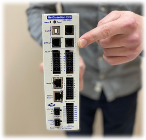
Our monitoring experts determined that a NetGuardian 216F would be a great match, as it gives us all of the features we need now, and it provides some room to grow with a couple of extra discrete inputs and an extra control as well. It also has fiber connectivity, so it is a perfect match for our monitoring needs in this example as it simplifies the network for us. We need to have a fiber node router to connect the hut to the rest of the network. This little workhorse of an RTU has a built-in fiber connection, which gets rid of the need to install a separate router at each location, and simplifies the system. Less gear in the chain equals less opportunity for failure.
The main feature of this unit is it can be ordered with Optical Zonu's iSFC Transceiver with Built-In Micro OTDR. This provides a large time and money-saving opportunity for this network. The iSFC transceiver with built-in micro OTDR is a fiber optic transceiver with a valuable key feature. It can tell you the location of your fiber break without requiring a tech to take the time to visit the location, haul out the fiber cable tester, and determine the location of the break. A NetGuardian 216F with the iSFC transceiver installed can identify where the break is in the fiber connection, and automatically report this to the technician via text or email. This eliminates the need for the tech to visit the remote location site to locate the fiber break.
Let's look at how this would provide bottom line results using the same example we just detailed.
The fiber break occurs between Locations 23 and 24. The event triggers the iSFC transceiver OTDR system to pinpoint the location of the break (18 miles from location 23) to the NetGuardian 216F. Immediately the NetGuardian 216F at location 23 reports a fiber break to the Central Office and is stored by the Master Station.
Our prior planning paid off because the master station is programmed to send a text message to the field tech on duty at the time of the event. Within less than 90 seconds of the fault, the tech receives a message that there is a broken fiber fault 18 miles from Location 23 and it's time to roll. (This example is based on the DPS T/Mon master station system. It is not the only brand in the marketplace, but is a good one, especially in this application).
An all of this before the first customer has a chance to even look for your call center's phone number. When they do finally call, your team can let them know the fault is identified and is being fixed even before they called.
In this article we have outlined a typical example of the planning that is involved in a new system build-out. However, often systems are not planned out from scratch with the latest technology. System integrators and network staff have to upgrade networks on the fly as they grow, as needs and funding allows.
Building in flexibility to a system is key to allowing for future growth and network needs. Careful planning in advance can maximize the value of gear you install when you can combine network elements into one ru (like we did when combining the fiber router, the RTU, and the LAN hub all in one device like the NetGuardian 216F). This kind of efficiency adds real savings to tight budgets and enhances system reliability by minimizing the number of network gear that can fail.
Do you have questions regarding your project plans? Call us! Our monitoring experts can help you save time and money while protecting your network.