Check out our White Paper Series!
A complete library of helpful advice and survival guides for every aspect of system monitoring and control.
1-800-693-0351
Have a specific question? Ask our team of expert engineers and get a specific answer!
Sign up for the next DPS Factory Training!
Whether you're new to our equipment or you've used it for years, DPS factory training is the best way to get more from your monitoring.
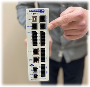
Reserve Your Seat TodayIf you are a network technician who needs to deploy or maintain SCADA equipment with DNP3 protocol, then you need practical information to make DNP3 work for you.
We have helped multiple clients throughout 30+ years in business to develop and work with DNP3 monitoring solutions. We know that to make DNP3 monitoring work for you, you need fast, specific answers.
Reliable, impartial answers can be hard to find in the internet. So, to help you, we are bringing DNP3 vital information to help you successfully implement and maintain a DNP3 remote monitoring system to manage your network.
The Distributed Network Protocol (DNP or DNP3) was introduced in 1993 as an immediately deployable solution for monitoring infrastructure status and to allow reliable remote control. Since then this protocol has achieved general acceptance and is now used by multiple different manufacturers in many applications.
DNP3 is based on an object model that reduces the bit mapping of data that is traditionally required by other less object-oriented protocols. It reduces the disparity of status monitoring and control paradigms usually found in protocols that provide almost no pre-defined objects.
Some people would say that any required object can be "built" from existing objects. However, having pre-defined makes DNP3 a more practical design and deployment framework for Supervisory Control and Data Acquisition (SCADA) engineers and techs.
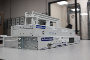
DNP3 is used between central master stations and distributed remote units. The master works as an interface between the human network manager and the monitoring system. And the remote unit is the interface between the master station and the physical equipment being monitored and controlled at the remote sites.
Both the master and remote use a library of common objects to exchange information. DNP3 has capabilities that allow it to be reliable even over media that may be subject to noise interference.
The DNP3 protocol uses 27 basic function codes to allow communication between master stations and remote units. Some of these function codes make it possible for a master to request and receive status information from a remote device. Other function codes allow the master to determine or adjust the configuration of a remote unit.
Many function codes are defined for a DNP3 master station to control the remote unit or equipment at remote sites. One function code is provided to enable the remote to respond without a request with an Unsolicited Message to determined events that happen in its deployed site.
Most of the communication is issued by the DNP3 master station to the DNP3 remote device. But, because the Unsolicited Message is initiated by a remote unit, its main function is to report an alarm. This message alerts the master as soon as an alarm occurs, so then you won't have to wait until the master issues a status request to learn about the alarm condition.
The DNP3 protocol framework includes a library of objects that are usually used in SCADA systems. These objects include:
Binary Inputs
They are used to report gear characteristics that have two different states. For example, power on or off or an access panel is open or closed.
Analog Inputs
This another common object is used to report characteristics that have a range of values. For example, exhaust fan speed can be anywhere from 40 to 400 RPM, or the main power can vary from 110 to 128 VAC.
This library makes it easy for the manufacturer to design the DNP3 remote responder to use these common objects to report to their master. It also makes it easier for masters to integrate the data collected from remotes and present it for decision making.
Without this framework of common objects, manufacturers must develop their own model for reporting status and providing control capability. These models are frequently different from one another, so they must be "compiled" into the masters and usually converted into some kind of common objects for efficient management. Another tool found in open frameworks is a proprietary interface or translation module to access and control the remote device.
Objects in the DNP3 library are divided into Groups and Variations. So, for instance, the Analog Input group has six variations to provide 16 or 32-bit integer or floating-point values with or without a status bitmap. The Analog Event group has eight variations to provide 16 or 32-bit integer or floating-point values with a status bitmap and with or without a timestamp. Keep in mind that the Analog Event group does not include variations without a status bitmap.
Now, let's take look at the structure of the messages that allow the communication between the master and the remote devices.
Basic serial telemetry protocols (such as TBOS) are byte-oriented, with a single byte exchanged to communicate. Expanded serial telemetry protocols (such as TABS) are packet-oriented with packets of bytes exchanged to communicate. The packets contain header, data and checksum bytes.
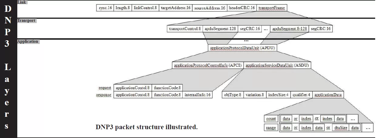
DNP3 is also packet-oriented and it uses the packet structure.
The master sends a Read request for an object or objects and the remote's response contains the requested information if available. The master sends an Operate command to produce the output actions associated with the selected object reference. And, as previously said, the remote sends an Unsolicited Message when a specific event happens.
Now let's focus specifically on the layered communication model used to exchange information.
The application layer combines an application service data unit (ASDU), a packaged object in itself, with an application protocol control info (APCI) block to make an application protocol data unit (APDU).
The transport layer breaks the APDU into segments with a maximum size of 16 bytes and packages them with an 8-bit transport control header and 16-bit segment CRC separators into a transportFrame.
The link layer can be mapped to the four-layer model developed by the Department of Defense with the DoD Internet Layer omitted.
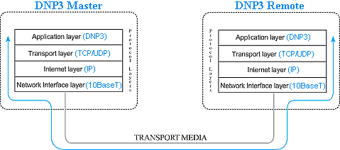
If the serial transport is used, the packet assembly is completed and placed on the transport media for delivery. If the packet will be sent over a LAN/WAN, the three DNP3 layers are rolled up into the application layer. The assembled packet is wrapped in the Transport Control Protocol (TCP) by the transport layer, which in turn is wrapped in the Internet Protocol (IP) by the internet layer. The User Datagram Protocol (UDP) can also be used but presents some additional issues related to reliable delivery in congested networks.
The fourth layer is the Network Interface layer where the assembled packet is actually interfaced to some type of transport media, such as twisted-pair copper, RG58 co-axial or fiber. While this multi-layer model may seem a bit confusing, it effectively isolates the tasks of communication and ultimately assists in designing and implementing a network.
To better understand the function of this layered model, let's take a look at a single DNP3 Read request over a LAN.
The DNP3 master wants to know the current status of the remote's power and prepares a Read request message for the appropriate object. After passing through all three DNP3 layers, the message is passed to the TCP/UDP transport layer. The transport layer adds a data block that identifies the master port from which the request is sent and the port on which it expects the remote DNP3 process to be listening for messages.
The packet thus formed is then passed to the IP layer. Here a data block containing the IP and Media Access addresses of the master and the remote is added before the entire assembled packet gets passed to the Network Interface layer. The Network Interface layer verifies media access and availability and places the packet on the media for transmission.
After working its way across bridges and through routers, based on the IP information, the packet finally arrives at the remote device. Here it passes through the same four layers in exactly the opposite order as it did at the master.
First, it is pulled off the media by the Network Interface layer. After confirming that the packet is intact and valid, the Network Interface layer simply passes it to the IP layer. The IP layer verifies the Media Access and IP Address and passes it on to the TCP/UDP layer where the target port is checked for connected applications. If an application is listening at the target port, the packet is passed to the Application layer. If the listening application is the remote DNP3 process, the Read request is passed through its three layers to validate the request and identify what information needs to be gathered.
The remote response then follows the identical path in reverse to reach the master.
Using the DNP3 protocol in a contemporary industry environment is an easy decision. DNP3 is a standard protocol that has wide acceptance in SCADA systems and is flexible enough for almost any application.
Deploying DNP3-enabled devices surely can help you have an effective monitoring solution, but this doesn't mean that any master or remote will be best for your scenario. Before you invest in a gear that won't properly take care of all your needs, it's important to take into consideration multiple factors. Some of them are:
Master stations sometimes present data in a graphical interface that gives you a good presentation of event and alarm detail for more than a single site or region.
If you will be relying on Unsolicited Messages in your system, ensure there is a clear event for each alarm. Creating this association can involve expensive custom development on your master system.
Avoid the allure of maintaining only an event log of newly reported Unsolicited Messages and a history log of acknowledged Unsolicited Messages.
If an Unsolicited Message represents an alarm condition, there should be continuing visibility to the alarm even if the Unsolicited Message is acknowledged. Imagine if a tech acknowledges an alarm message, but fails to correct the alarm condition - who would know the alarm is still standing?
Masters should support organizing alarms by a wide variety of characteristics, such as location, equipment type, and severity. The same alarm should be able to post to multiple categories.
The presentation of sorted and filtered alarms should depend on the user logged on - the generator maintenance team doesn't need to wade through lists looking for generator events and alarms.
Look for a master that supports the advanced status monitoring features, such as notification escalation, nuisance alarm silencing, automatic control relay operation, and automatic notifications by email or text message.
If your remote device is powered from a single source, then your critical monitoring is vulnerable. Losing this single source of power compromises the continuous monitoring of your mission-critical gear. If your installation does not have dual power sources, make sure the equipment is compatible with an external uninterruptable power supply. Also, make sure to monitor that primary power.
If a network failure compromises the collection of data, your remote equipment should provide for local visibility. Turn the worst-case scenario of having to dispatch techs to a critical remote site into a much better case by ensuring that they will be able to browse to your remote units and have local SCADA until the network is restored.
Understanding the DNP3 protocol is very important to maintain the health of your remote monitoring system. However, if you are most companies, that is probably not the only protocol you have in your network.
You need to make sure all your remote equipment supporting different protocols can work together - while still being able to take advantage of all their features and capabilities. Network integration is the best way to bring all your incompatible systems under only one monitoring umbrella. This saves your budget because it helps you get modern capabilities without replacing your gear.
We've put together the Five Steps to Successful SNMP-Legacy Integration guide to help you learn how you can integrate all your incompatible monitoring devices. Download your free PDF copy and learn how to improve your network visibility.
Want to know more about custom-fit solutions and how they can benefit your monitoring needs? Don't waste time reading. Instead, speak with one of our engineers and ask questions in real time.
Help us connect you to the right engineer by filling out this quick questionnaire. Simply leave your contact information to get started, and we'll call you back. Most preliminary discussions are about 15 minutes, and afterward, we'll send you a custom application diagram of a recommended solution that'll make it easier to justify your project to management.

Morgana Siggins
Morgana Siggins is a marketing writer, content creator, and documentation specialist at DPS Telecom. She has created over 200 blog articles and videos sharing her years of experience in the remote monitoring industry.